

Categorization:Product Information
The USB Type-C connector has the potential to become the sole data port for many laptops and smartphones in the future, but these USB-only devices will still need to connect to non-USB devices such as monitors and TVs. Switching between USB and other high-speed formats in a single connector poses challenges for designers, including switching between pin functions, providing protection from external transients such as ESD, and maintaining signal quality. the USB Type-C standard meets these needs by defining an Alt Mode method of operation, which dynamically changes the function of pins to allow the use of non-USB data protocols. data protocols.
This article explores the various standards that enable USB Type-C connectors to stream HDMI and other non-USB formats, and provides key design considerations for adding HDMI Alternate Mode functionality to the USB Type-C interface.
The HDMI Forum manages alternate mode operation for USB Type-C environments.The latest USB standard, released in late 2016, consists of three parts:
The USB Type-C connector specification makes some significant changes to the familiar Type-A and Type-B versions. For the casual observer, two features stand out:
Measuring 8.3mm x 2.5mm, Type-C is much smaller than the USB Type-A and -B connectors, but contains 24 pins, compared to four in earlier versions.
Type-C connectors are reversible and work in any orientation. For this reason, the connector pin arrangement is symmetrical; no matter which row is on top, all signals are in the same relative position.
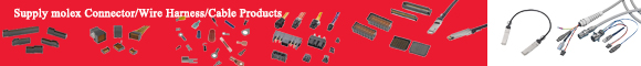
The USB Type-C specification allows communication modes with legacy USB 2.0 systems via the D+/D- and VBUS/GND pins. The pinout also includes pins for two other new features defined in the specification, including alternate modes. Figure 1 shows the standard and alternate mode mapping for Type-C connectors.
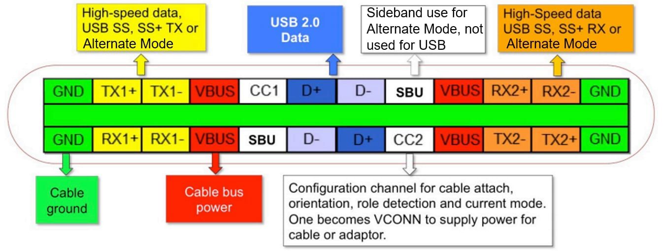
Figure 1: USB Type-C connector pinout showing alternate mode mapping. (Source: Texas Instruments)
The USB Type 3.1 specification updates the electrical performance of USB by increasing the data rate to 10Gbps (called SuperSpeed+ in the specification). This requires two differential TX and RX pairs dedicated to high-speed data. The specification also increases the baseline power capability to 5V at 150mA.
The USB Power Delivery specification (USB PD) defines alternate mode operation, but it also increases the amount of power available to 100W and greatly expands the range of power delivery options available to designers. When used with an active USB Type-C cable, USB PD adds bi-directional power flow between the two devices; the power flow can even be reversed in real-time due to the communication channel carried on the Type-C Configuration Channel (CC) pin.
Although the three specifications are separate, HDMI-enabled USB systems must support both Type-C and USB PD specifications. In addition, each remapped pin must support the data rate of its corresponding HDMI 1.4 feature.
HDMI 1.4 has six data channels running at four different speeds:
HDMI Ethernet and Audio Return Channel (HEAC): A high-speed, bi-directional data communication that supports 100Base-TX (100Mbps) Ethernet. HEAC includes a streaming audio component that complies with IEC 60958-1.
TMDS (Transition Minimized Differential Signaling): Three differential channels for high-speed video and data transmission.HDMI 1.4 has a maximum throughput of 10.2Gbps or 3.4Gb per channel.
DDC (Display Data Channel): A communication channel based on the industry-standard I2C protocol, with a standard rate of 100kbps; it enables the source device to recognize supported audio/video formats.
CEC (Consumer Electronics Control): Allows the user to control up to 15 low-speed channels of compatible devices. The channel complies with CENELEC EN 50157-1
The standard HDMI Type-A connector is shown in Figure 2; Figure 3 shows the new pin definitions for the USB Type-C connector in HDMI alternate mode. The implementation maps three TMDS pairs and their clock signals to eight USB TX/RX pins. The two SBU pins now carry the HEAC channel and the CC pin carries the low-speed CEC signal. Note that the D+/D- pairs are not affected by this conversion, so the USB 2.0 data channel can still run in parallel with HDMI.
Figure 2: The HDMI Type A connector has 19 pins, including the three high-speed data channels as a shielded twisted pair.
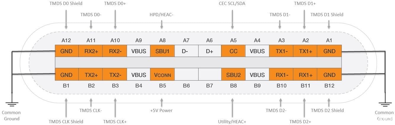
Figure 3: Pin mapping for HDMI in USB Type-C standby mode (image source: HDMI.org)
The USB PD specification defines the sequence of events required to enter standby mode. When a user connects an active Type-C cable between two USB PD-enabled ports, a series of negotiations take place over the CC line (Figure 4). The negotiation determines whether USB or alternate mode is to be used and which alternate mode standard applies; a specific set of vendor-defined messages (VDMs) identifies the standard to be used.
Figure 4: When a USB PD-enabled port first recognizes the presence of another USB PD port, negotiation occurs to determine the power supply protocol and data format to be used. (Image credit: Texas Instruments)
Although not required for HDMI operation, the negotiation sequence also includes other USB PD features such as the desired power level and direction of power flow. Once the initialization sequence establishes HDMI as the desired protocol, both ports remap their pins as needed and HDMI Alt Mold operation begins.
What hardware components are required to add HDMI to a USB Type-C port? Figure 5 shows a block diagram of the USB PD port with the alternate mode components highlighted. Note that even if the application does not specify a USB PD power level, agreeing to Alternate Mode requires negotiation over the CC line, so the USB PD PHY and PD Manager must still be included:
The Alternate Mode Physical Layer Device (PHY) takes the video information from the High-End Graphics Processing Unit (GPU) and encodes it onto the three TMDS differential data lines.
The Alternate Mode Multiplexer (MUX) allows switching between HDMI AM and USB implementations. For HDMI applications, it connects the HDMI signals to the correct Type-C connector pins; for USB 3.1 applications, it connects the RX/TX signals and swaps them according to cable orientation.
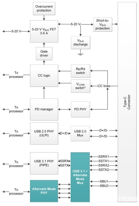
Figure 5: Spare mode via USB Type-C requires two additional modules, shown in green. (Image credit: Texas Instruments)
The HDMI Alt Mode specification is new, so chipsets designed specifically for this application are still under development. However, DisplayPort Alt Mode parts are readily available and can be used with the addition of an HDMI format converter. Figure 6 shows a block diagram of a USB Type-C port that supports USB, HDMI Alt Mode, and the full USB PD specification.
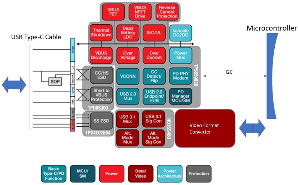
Figure 6: USB Type-C/HDMI Port Block Diagram
Two devices form the basis of the design: first, Texas Instruments' TPS65982 standalone USB Type-C and PD controller performs multiple tasks:
It detects the insertion of the USB Type-C cable and its plug orientation.
It negotiates the power supply function and passes the information via I2C to the monitoring microcontroller that determines the mode of operation.
It configures Alt Mode settings for the multiplexer to route USB or HDMI signals to the correct destination.
During operation, the TPS65982 also manages USB power routing and control.
Second, Texas Instruments' (TI) HD3SS460 high-speed, bi-directional, passive 4×6 multiplexer/demultiplexer switches between alternate and USB modes and adapts to connector flip-flops.
The final building block is a video converter for switching from DisplayPort to HDMI format.
In addition to the main modules discussed above, three in particular deserve careful consideration: the first two protect components from electrical overvoltage, and the third improves overall system performance.
Because USB ports are connected to the outside world, the design must provide protection against potential ESD shocks when the user plugs or unplugs the cable, but different pins require different ESD solutions. At gigabit data rates, designers must take special precautions to maintain signal integrity. Any additional circuitry added to the high-speed data path, such as ESD protection devices, must add minimal capacitance to the line; it must also maintain impedance matching throughout the signal path, as any mismatch can cause reflections that can increase jitter and degrade signal quality. Pins that carry low-speed data, such as SBUs and CCs, are less sensitive to added capacitance or impedance mismatch.
Eight TX/RX pins carry high-speed data channels in USB and HDMI modes: a USB 3.1 channel for USB operation and three TMDS channels and clocks for HDMI AM operation.
The Texas Instruments TPD4E02B04 transient voltage suppression (TVS) device protects high-speed data pins. It is a four-channel, bi-directional ESD protection diode array with an I/O capacitance of only 0.25pF per channel, and utilizes the industry-standard USON-10 package and flow-through routing to match the alignment impedance.
ESD protection for the low-speed pins is included in a separate device, discussed next.
The USB Type-C connector has a pin pitch of only 0.5mm. this increases the likelihood of pin-to-pin shorts compared to earlier Type-A connectors. The pins adjacent to the V BUS pin (SBU and CC) are particularly at risk, especially if the USB/HDMI port supports the full USB PD specification, which allows the V BUS pin to carry up to 22V. This sustained voltage can not only appear on neighboring pins in the event of a short circuit, but can also generate ringing voltages of up to 44V during a hot-plug short to the V BUS.
Texas Instruments' TPD8S300 USB port protector (Figure 7) provides overvoltage protection against VBUS short-circuit events on the CC and SBU pins and protection against voltage ringing. Although these and other pins are not as sensitive to additional capacitance as the high-speed pins discussed earlier, they still require ESD protection. the TPD8S300 protects the SBU and CC pins and provides additional ESD protection for the two USB2.0 D+/D- pairs.
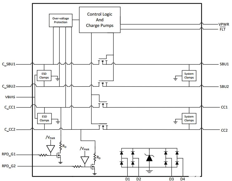
Figure 7: The TPD8S300 block diagram shows the series FETs and control circuits used to protect the SBU and CC pins from a VBUS short event, as well as four additional channels of ESD protection. (Source: Texas Instruments)
Adding components to prevent ESD and V BUS shorts can have an impact on high-speed HDMI or USB signals: despite designers' best efforts, signal quality inevitably suffers as it travels through the board. IC pin parasitics, PCB alignments, and via holes can degrade signal quality before the signal reaches the output pins.
Adding an adapter driver to the signal chain before the Type-C connector is a cost-effective solution to maintain good signal quality at high data rates. The adapter driver boosts the signal output and includes linear equalization to compensate for channel loss. In USB Type-C systems, it can help pass compliance tests and improve device interoperability when used with low quality or very long cables.
Texas Instruments' TUSB1046 combines an Alternate Mode multiplexer and adapter driver into a single device. The part includes a linear adapter driver that can support data rates up to 8.1Gbps per Alt Mode channel, more than enough for the 3.4Gbps of HDMI 1.4. Although the TUSB1046 was originally designed for DisplayPort use, it is protocol agnostic. Figure 8 shows a DisplayPort four-channel setup repurposed for the three HDMI TMDS channels and the TMDS clock.
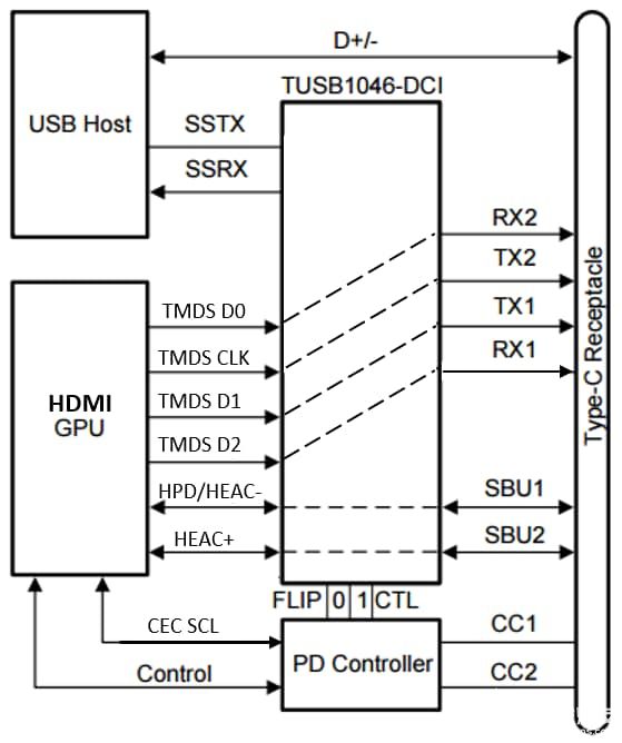
Figure 8: TUSB1046 adapter switch configured for HDMI AM applications: The device can also support USB 3.1 SuperSpeed+ in normal mode. (Source: Texas Instruments)
USB Type-C is the latest version of the popular standard that is becoming the standard for high-speed data communication in consumer devices such as laptops and smartphones. Utilizing USB's alternate mode capability, HDMI is the latest high-speed data standard to release a specification defining its use in the USB Type-C environment. Designers can expect to see other popular video standards join DisplayPort, Thunderbolt, MHL and HDMI in the alternate mode trend.
Because HDMI is such a popular standard, expect to see alternate mode chipsets dedicated to HDMI appear soon. Regardless of the particular circuit module, however, many of the issues discussed in this article are basic engineering problems that must be addressed in any system with similar performance.
“Without the consent or authorization of this site, no one shall reproduce, reprint, distribute, cite, change, broadcast or publish the content in whole or in part in any form, nor shall there be any other violation of the copyright of this site.