

Categorization:Product Information
The deployment of 5G networks and their connected devices will put higher requirements on the current connector structure. For high-volume manufacturing, investments in connector technology must strike a balance between performance, size, and cost to thrive in the market. For gigahertz applications, the need to isolate internal and external sources of electromagnetic interference (EMI) is a unique challenge for 5G applications. Take 5G mobile phones as an example. It contains multiple subsystems (GPS, Wi-Fi, cellular sub-6 GHz, and mmWave 5G) that need to work together to maximize the antenna loss issue to a lower level and ensure the interoperability of the entire subsystem. The millimeter-wave subsystem of 5G phones is designed for efficient millimeter-wave radiation and must also be located near sensitive CPU cores and passive antennas. This can lead to problems with electromagnetic compatibility (EMC). There are many solutions to alleviate these problems. However, these solutions tend to be CNC-machined solutions with larger and heavier highly shielded coaxial structures. 5G devices for consumer use require a careful balance between performance, size and cost. 5G UE devices must break through the limitations of miniaturization while generating greater performance to support these next-generation devices. The trend shows no signs of slowing; Just as EMC's problems show no signs of getting simpler. Microstrip and stripline small RF coaxial connectors, combined with cable grounding and harness management solutions, represent a range of progressive EMI solutions. Small, shielded and inexpensive, these components play a key role in the system EMI compliance strategy of successful product engineers. Industry standard procedures for engineering design are: achieving performance targets; The balance between component size and cost constraints can only be optimized after performance targets are achieved. However, as frequencies continue to inevitably rise, electromagnetic interference suppression and isolation became a key "primary consideration" at the beginning of the project. Fortunately, there are progressive and effective solutions that can help reduce EMI system emissions to acceptable levels. This component selection is a low-cost, microstrip version of the board-to-line solution (see Figure 1). It provides basic RF coaxial line connections for PCB microstrip structures. Some RF designs can accept microstrip performance and only occupy 2 metal layers on the PCB, thus reducing PCB cost and thickness. However, for higher frequencies, it may not sufficiently suppress EMI radiation to pass compliance. In cases where microstrip transmission lines are insufficient to meet EMI performance requirements, a 3-layer stripline transmission structure may be required. In these cases, a low-back, high-performance RF stripline connector (see Figure 6) is the solution. In high-performance environments, where additional EMI countermeasures must be employed, adding an SMT ground clamp (see Figure 3) can help. This is an excellent low-cost tool that can greatly suppress EMI emissions, thus minimizing the effort of PCB layout redesign even more. By comparing Figure 4 and Figure 7, it is easy to see the related improvements in shielding effectiveness after adding SMT cable grounding clamps. We used an Ansys ® HFS ™ S 3D electromagnetic simulation to carry out a closer examination of the shielding performance in the following four cases:

1: Case 1-Preset required EMI performance, microstrip transmission line:
The microstrip transmission line chassis is built by using microstrip RF connector, and the simulation is carried out in HFSS. As shown in Fig. 2, the microstrip structure allows radiation to escape the guided wave structure.
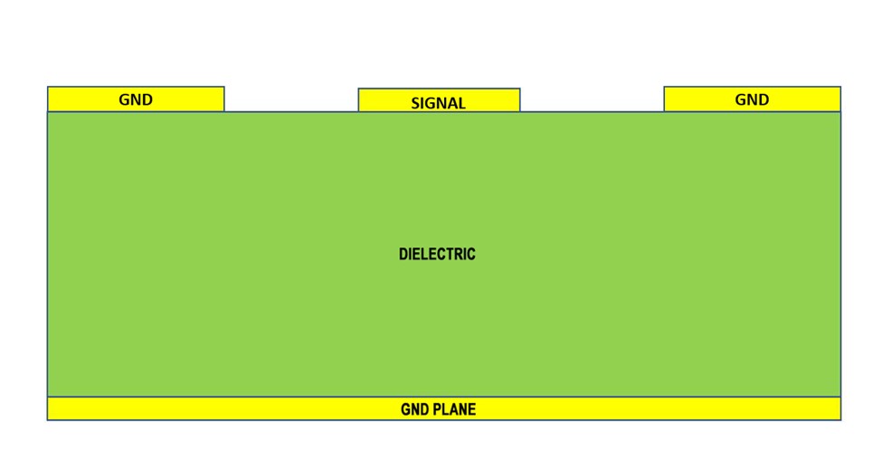
Figure 1: Microstrip cross-sectional view
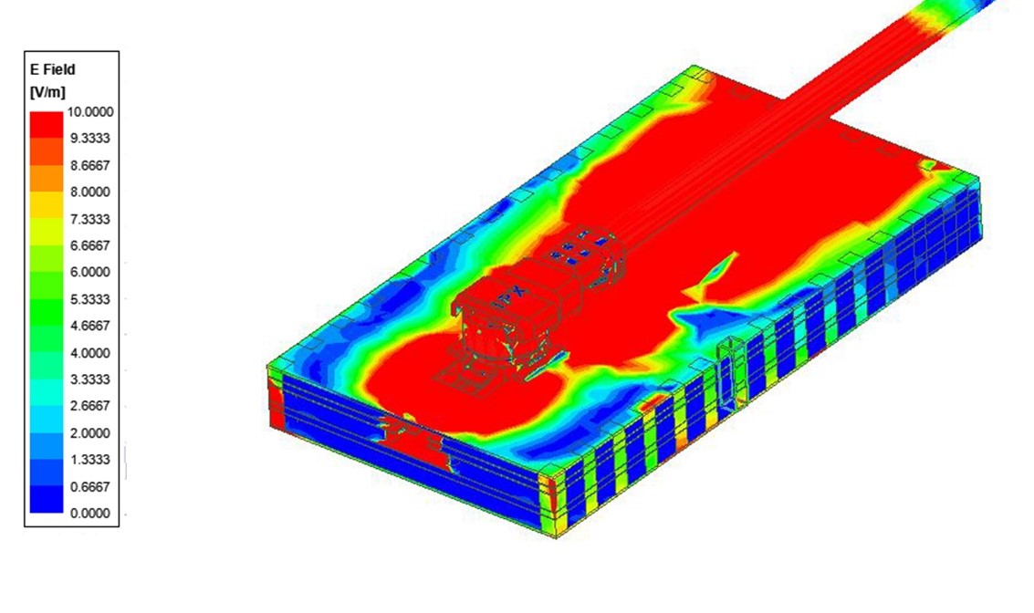
Figure 2: I-PEX MHF ® 4L small RF coaxial connector connects a microstrip waveguide structure, which has inherent radiation characteristics, but still suffers from shortcomings in EMI suppression.
---------------------------------------------------------------------------------------------------
2: Case 1b-RF Microstrip Connector with Additional SMT Ground Clamp:
With the increase of SMT ground clamp, EMI radiation is confined to the area around the emission point and decreases significantly along the microstrip line length (see Figure 4). It should also be noted that while this does not create complete shielding, it does not require an additional ground plane and the associated costs of new board rotation.
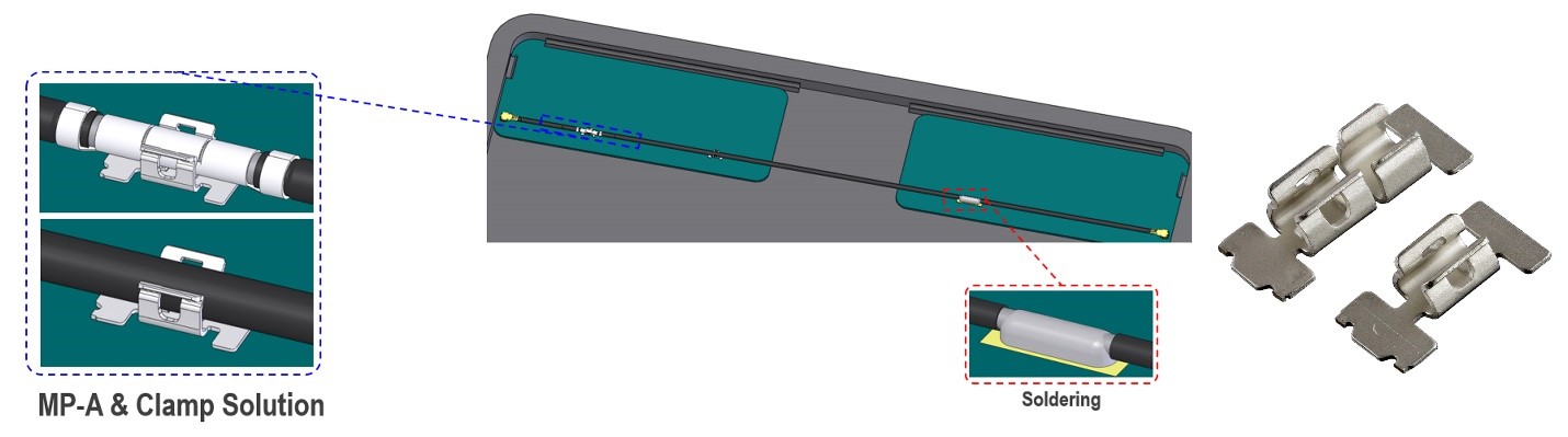
Figure 3: EMI simulation case 1b, using I-PEX ® MP-A SMT ground clamp to drain interference current from the very thin coaxial cable shield to the PCB ground plane.
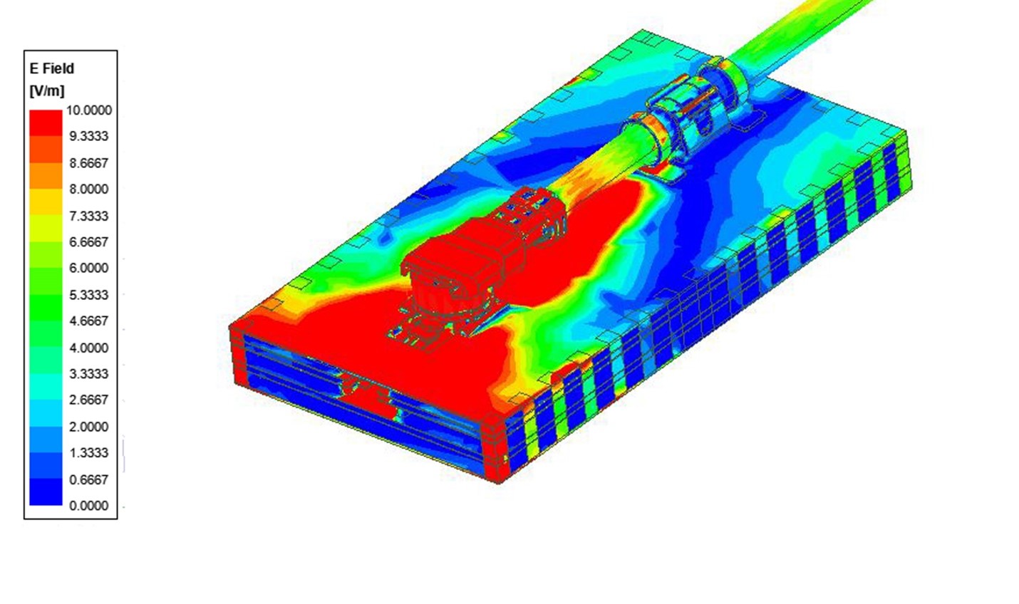
Figure 4: EMI simulation case 1b uses the I-PEX ® MP-A SMT ground clamp to drain interference current from the very thin coaxial cable shield to the PCB ground plane, thus limiting the area of the EMI leakage area.
---------------------------------------------------------------------------------------------------
3: Case 2-Requires a higher level of EMI performance, requires stripline transmission lines and RF stripline connectors:
Durable value designs typically use a 3-layer stripline transmission line construction (see Figure 5). To this end, a new stamped connector solution came into being (see Figure 7). The signal conductors are completely contained within the boundaries defined by the ground plane on both sides of the signal layer, which provides better shielding in the PCB design (see Figure 8).
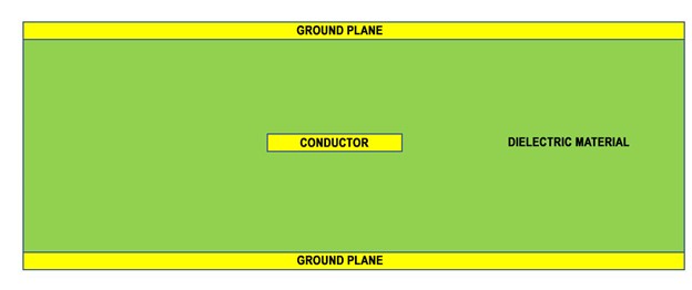
Figure 5: Stripline (3-ply) cross-sectional view.
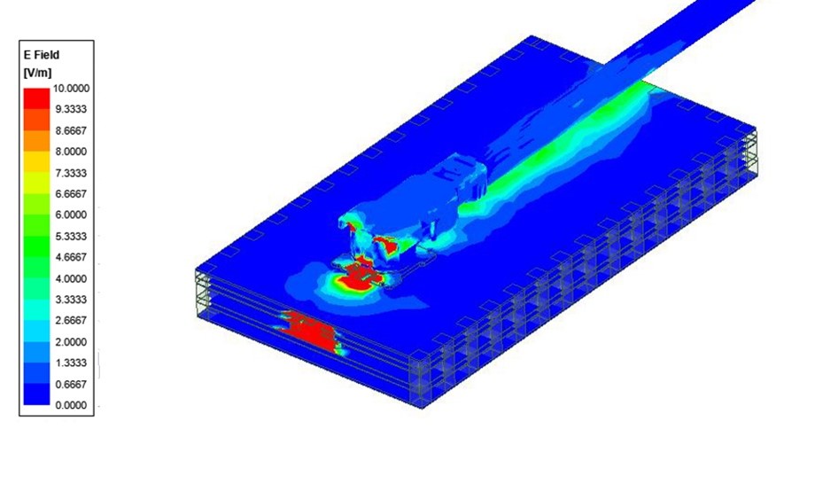
Figure 6 ": I-PEX MHF ® 7S extremely small RF coaxial connector and cable connected to the stripline transmission structure, allowing for a very small degree of EMI leakage on the upper PCB ground plane.
---------------------------------------------------------------------------------------------------
4: Case 2b-Stripline Transmission Lines and RF Stripline Connectors with Additional SMT Ground Clamp Provide Higher Degree of EMI Rejection:
For extremely sensitive systems that require even greater EMI shielding rejection performance, the addition of SMT ground clips further enhances the performance of RF shielded striplines to small RF coaxial connectors (see Figure 7).
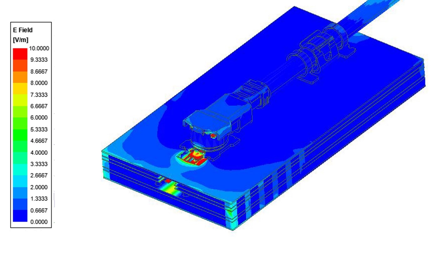
Figure 7: Stripline RF lockable connectors enable higher levels of EMI mitigation in addition to SMT ground clips.
---------------------------------------------------------------------------------------------------
5: Conclusion:
Continuous improvement of EMI shielding effectiveness can be achieved by using: 1. Microstrip small RF coaxial connector (see Figure 2) 2. Microstrip small RF coaxial connector + SMT cable ground clamp (see Figure 4) 3. Stripline small RF coaxial connector (see Figure 6) 4. Stripline small RF coaxial connector + SMT cable ground clamp (see Figure 7) With the rise of 5G equipment, we are seeing increasing performance pressure on connector technology. The niche position of stamped connector solutions has become a challenge posed by 5G: performance, space, and cost. The development of this technology will inspire new solutions to emerge now and in the foreseeable future of 5G.
---------------------------------------------------------------------------------------------------
6. Brief description of World Trade Electronic Products Network Company and its products sold:
World Trade Electronic Products Network is a professional, accurate and vertical comprehensive product sales platform for the electronic industry focusing on the supply, demand and sales of connector wiring harness and cable products! Specializing in the production/sales of {Connector Harness Cable Products}; If you want to buy or know which connector harness cable product solutions we can provide, please contact us through the following methods.
“Without the consent or authorization of this site, no one shall reproduce, reprint, distribute, cite, change, broadcast or publish the content in whole or in part in any form, nor shall there be any other violation of the copyright of this site.