


Categorization:Product Information
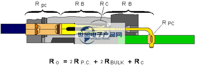
The degradation mechanism of connectors is very important to the performance of connectors, and it is very important to the performance guarantee of related products. What is the degradation mechanism? What factors cause the connector to fail? We will continue to explore this issue. Connectors are used for the connection between two separate systems. Separability is necessary for many reasons, from ease of manufacture to improved performance. However, when mated, the connectors should not add any unnecessary resistance values between the systems. Increasing the resistance value may distort the signal or cause power loss and cause system failure. Connector degradation mechanisms are important because they are a potential source of increased resistance and, therefore, functional failure over time. Let's start with a brief review of the connector's resistance. Fig. 1 shows a cross section of a universal signal connector. The equations in Figure 1 represent the various sources of resistance within the connector. Ro is the overall resistance of the connector and is the resistance between the end of the conductor and the PCB connector pin solder point. The Rp. C of the two permanently connected resistances is the resistance between the crimp connection point and the corresponding pin. Similarly, the two bulk resistances (Rbulk) refer to the bulk resistance of the rear contact and the parallel bulk resistance between the two columns of the connector; there is also a contact resistance Rc at the interface or separation. The overall connector resistance is the sum of the individual constant connection resistances, the back contact and cavity connector resistances, and the separable contact resistance, since all of these resistances are in series.
---------------------------------------------------------------------------------------------------
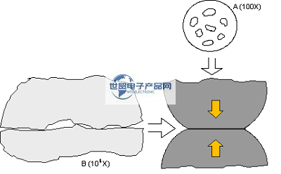
For the sake of discussion, let us assume that the measured total resistance value Ro is 15 milliohms. With this assumption in mind, we guess at the relative contribution of the lower permanent connection resistance, the body resistance, and the contact resistance at the separable point to the overall connector resistance. In this example, these values are the resistance values of a typical soft-shell connector, and the body resistance will account for the majority of the total resistance, which is close to 14 milliohms. The permanent connection resistance is several hundred microohms, and the other is the contact resistance at the separable place. While the bulk resistance of the connector contacts is the largest contributor to the connector resistance, it is also the most stable. The bulk resistance of a single contact is determined by the material from which the contact is made and its overall geometry. In this simple example, the resistance, considering the length of the conductor, can be calculated by Rcond. = R l/a. In this equation, R is the resistivity of the conductor (which can also be the spring material in the connector), "l" is the length of the conductor, and "a" is the cross-sectional area of the conductor (or the geometry of the spring in the connector). For a given material, such as phosphor bronze and contact geometry, these parameters are constant, so the overall resistance of the connector is constant. The permanent connection resistance and the interface or separable connection resistance are variable. These resistors are susceptible to a variety of degradation mechanisms, which will be discussed in a later paper. It should be pointed out that connectors are affected by many factors, such as harsh environment, heat, life, vibration and so on. And the total connector resistance may vary from the original 15 milliohms to, for example, 100 milliohms, with the variation in resistance occurring primarily in the separable and permanently connected resistors. The separable interface resistance is the most easily degraded because forces and deformations, etc., are generated at the separable. In simple terms, two major separable interfaces are required to generate certain forces and deformations. The bite force of the connector is the first and most obvious requirement. For high PIN count connectors, the bite force of the individual PIN bits must be controlled, and the contact normal force is one of the primary parameters that is subject to this requirement. For example, a separable connection has a contact force of tens to hundreds of grams, while an insulated crimp connection, or IDC, has a force of the order of thousands of grams, as does a corresponding force pressed into the connection. The high force in such a permanent connection provides greater mechanical stability and a lower resistance value than that of a separable connection. In the same way, a higher permanent connection force allows a greater deformation of the contact surface than a separable connection. Crimp connections are the most obvious examples, such as significant deformation of crimp terminals and significant deformation of individual conductors. Both the force of the crimp connection and the corresponding PIN allow for a greater deformation of the contact surface. As with higher forces, the larger surface deformations of the permanent connections reduce their resistance compared to the separable contact resistance. The deformation of the separable interface is also limited by another separable interface requirement: fit durability. High surface deformation generally results in high surface wear, which in turn may result in loss of contact coating, such as gold or tin on the contact surface. The loss of this coating will increase the corrosion sensitivity of the contact surface, which will be discussed in a future article. The combination of separable interface bite force and bite durability limits the deformation and mechanical stability of the separable interface, and is also responsible for the lower electrical stability of the separable interface compared to a permanent connection. In general, the larger the contact area between two surfaces, the lower the resistance of the interface. Indeed, for the resistance of the length of the conductor, the contact area between the two surfaces is similar to the equation Rcond. = R l/a. Because separable connections have a lower contact area than permanent connections, they have a higher electrical resistance. In summary, the reduced force of the separable connection results in reduced mechanical stability and the reduced contact area results in higher electrical resistance compared to the permanent connection. These problems, namely, the decrease of contact force and the decrease of contact area, directly affect the degradation sensitivity of the separable contact interface. Figure 2 shows an enlarged schematic view of the separable contact interface. The figure shows that all surfaces are rough on the microscopic scale of such a contact interface. This means that the contact interface itself will consist of a distribution of contact points called a points or bumps, rather than a complete area contact. This uneven structure is responsible for the increase in contact interface resistance. The reduced contact area, including the distribution of points a over a certain geometric area, depends on the geometry of the contact surface. A type of resistance, called constriction resistance, results from the current being squeezed to flow through a single point a. The shrinkage resistance can be reduced by increasing the contact area in various ways, but it can not be eliminated. Therefore, the connector always adds some resistance to the electrical system. From this perspective, the primary goal of connector design is to control the size and stability of the resistor.
---------------------------------------------------------------------------------------------------
As previously mentioned, the magnitude of the interfacial resistance depends on the contact area created when the plug and receptacle contacts are brought into contact with each other. There are two main factors affecting the stability of contact resistance: the disturbance of contact interface and the corrosion of point a. How these factors affect the mechanism of connector degradation will be discussed later. In summary, these mechanisms include: 1. Corrosion occurs at and around the contact interface, thereby reducing the contact area. There are two corrosion mechanisms: surface corrosion, which directly affects the contact area, and induced or fretting, which increases the susceptibility of the contact interface to corrosion. 2. The integrity of the contact plating is lost due to insufficient plating or plating wear, thereby increasing the susceptibility to corrosion. Most connector contacts are plated with a surface layer of a precious metal, such as gold, or a common plated surface, typically tin. One of the main purposes of these coatings is to protect the contact substrate, usually a copper alloy, from corrosion. The corrosion susceptibility of noble and non-noble metals is different and will be discussed separately later. 3. Loss of contact force, resulting in reduced mechanical stability and contact interface susceptibility to fretting. The main mechanism leading to the reduction of the contact force of the connector is the excessive contact stress and stress relaxation. Stress relaxation is the loss of contact force over time due to time/temperature effects.
---------------------------------------------------------------------------------------------------
2、 on the World Trade Electronic Products Network Platform and Sales Product Profile: World Trade Electronic Products Network-professional agent/production/sales of various { connector | harness | cable products }; If you have relevant [connector | harness | cable products] procurement/purchase needs or want to buy/know what connector | harness | cable products solutions we can provide, please contact our business personnel below; if you have relevant [connector | harness | cable products] sales/resources and promotion needs, please click "Business Cooperation ←" to negotiate with the specialist!
“Without the consent or authorization of this site, no one shall reproduce, reprint, distribute, cite, change, broadcast or publish the content in whole or in part in any form, nor shall there be any other violation of the copyright of this site.