Categorization:Product Information
The system design is becoming more and more miniaturized, but the demand for power supply is increasing, which brings great challenges to design engineers. This means that the power connector must accommodate two contradictory necessary conditions at the same time, that is, the design must be more compact in addition to increasing the power supply. When screening the dazzling array of power connectors on the market, I don't know how to start. Take the key feature-rated current as an example, which contains a lot of knowledge. The rated current is the amount of current that causes the female terminal to raise temperature specifically, generally 20 °C or 30 °C. To use this data correctly, you must not only understand the test method, but also pay attention to the test environment. For example, some simply test a pair of female terminals and male pins that are connected but not installed in the housing. As we all know, the factors that affect the temperature rise of connectors include contact resistance, current amount and heat dissipation channels. In practical application, the male pin and female terminals are installed in the housing. Therefore, the heat dissipation channel is drastically reduced. In addition, multiple contact pairs are generally used at the same time, and the rated current peak value cannot be set as the working current of the connector.
------------------------------------------------------------------------------------------------------
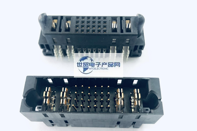
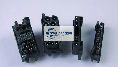
From the manufacturing point of view, most of the traditional power connectors are lathed. Based on the increasingly mature stamping technology, a new generation of stamped power connectors has been derived. In contrast, the lathe machining process is simpler, the grinding tool setting time is short, and it is a more flexible production technology. Although the stamping process is expensive, when it is put into mass production, its cost is comparable to that of lathe processing. In particular, the stamping technology allows local electroplating, which is an option that lathe processing cannot provide. From the perspective of quality, under the condition of long-term mass production, stamping ensures a certain degree of quality stability, which cannot be compared with lathe processing. From the assembly point of view, the methods of circuit board assembly include crimping, surface mounting or welding; Cable assembly methods include screw connection, welding, winding, rolling and IDC (commonly known as puncture connection or insulation displacement connection). To choose a suitable connector, not only the price of the connector should be considered, but also the suitable assembly technology should be considered more importantly. Solder connectors are naturally cheaper than surface mount and crimp connectors because they do not require high-temperature resistant plastic housings and do not require special crimp areas for pins. However, if there are all surface mount components on the single board, it is more cost-effective to choose surface mount power connectors. In terms of wiring, screw connection, welding and winding must be assembled manually, while rolling and IDC can choose assembly equipment on the market to quickly and accurately assemble connectors and cables. Compared with rolling joint, IDC has stricter requirements on the size of cables. The size and hardness of cable conductors and insulation layers must meet the specifications of relevant IDC connectors to avoid damage to the connectors and ensure the ideal electrical connection between cables and connectors. If it is used in high vibration working environments, rolled cable connectors should be selected. Other factors that need to be considered include the working environment temperature and whether high-temperature resistant cables should be used. ERmet power module current derating curve In fact, the most critical design of the connector lies in the contacts formed by the female terminal and the male pin. Poor design, manufacturing process, unsuitable base materials and electroplating layers can all lead to unsatisfactory contacts or even failure to form contacts. On the contrary, excessive clamping positive force will lead to excessive wear of the surface coating of the connector and shorten its mechanical life, that is, the number of plugging and unplugging. The contacts are designed with lathe [Industrial Electrical Network-cnelc] circular pins and terminals, such as European DIN41612 and ERmet 2mm M type power terminals, stamped double-bar terminals and pins, such as 2mm HM power modules, SMC connectors, etc., male and female double-bar terminals in the same body such as: MicroStac, etc. The surface coating materials include gold, palladium, nickel, silver, tin, etc. Silver has high electrical conductivity, but is prone to discoloration, particularly in sulfur-containing environments. If it is slight, it only affects the appearance, and if it is severe, it reduces the electrical conductivity. Palladium-nickel has high hardness and low porosity, so it has good corrosion resistance. Gold has high chemical stability, low hardness and high cost. In contrast, each has its pros and cons. The stamped double-bar terminal has two different power connectors in terms of configuration. Signal terminals on synthetic connectors generally account for the majority, while power terminals account for the minority. As for simple power connectors or power modules, the terminals are all high-current terminals. Traditionally, power connectors are mostly designed exclusively and are different from brand to brand. In view of the increasingly demanding demand for power connectors, various standards gradually include power connectors, resulting in standard power connectors, such as: multiple types of D-Sub, D, E, F, H and M in European DIN41612 Type connectors, 2mm HM M-type connectors and power modules, ATCA power connectors. Typical examples of synthetic connectors include: M-type European connectors, 2mm HM M-type connectors, and D-Sub connectors. For example, the ERmet 2mm M-type corner female connector offers 55 pins (5 rows x 11 rows of pins) and is equipped with three special pin chambers for power or coaxial terminals. Such connectors can be used alone or in combination with other 2mm types such as A, B, C, L or N types. In contrast, the ERmet M-type vertical male connector has up to 77 pins (7 rows x 11 rows of pins), of which two outer rows (22 pins) will be connected to the shield plate of the female connector. Correspondingly, the male connector also has three special pin chambers for placing power terminals or coaxial terminals. Examples of simple power modules include 2mmHM power modules, MicroSpeed power modules, and ATCA power connectors. In addition, there are board-to-wire power connections-MiniBridge and MaxiBridge. In order to allow the power connector to provide a higher rated current, various connector manufacturers are constantly improving the design of the power connector, including selecting new copper alloy-based materials with stronger conductivity, innovating the design of female terminals and male pin contacts and improving the heat dissipation performance of the connector. In line with various working environment conditions, connector manufacturers have also developed various power connectors suitable for high vibration systems, dustproof and waterproof, and with locks for special purposes. There are even connectors with different colors that mean different mechanical codes to prevent operators from inserting them by mistake. In view of the increasing automation of PCB assembly processes, tape-and-roll packaging and pre-installed grip pads are also increasingly common. With the rapid development of electronic technology, it is estimated that there will be more and greater breakthroughs in the design of power connectors in the future. As long as the right power connector and good PCB design are selected, system design engineers will definitely be able to launch better products.
---------------------------------------------------------------------------------------------------------------------------------------------------------------------------------------------------------------------------------------------------------------------------------------------------------- If you have related [connector wiring harness and cable products] purchasing/purchasing needs or want to purchase/understand which connector wiring harness and cable product solutions we can provide, please contact our business staff below; If you have related [Connector Wiring Harness Cable Products] sales/resources and promotion needs, please click "→ Business Cooperation ←" to negotiate with a dedicated person!
“Without the consent or authorization of this site, no one shall reproduce, reprint, distribute, cite, change, broadcast or publish the content in whole or in part in any form, nor shall there be any other violation of the copyright of this site.