

Categorization:Product Information
Vehicle power distribution and grounding design are the core parts of automobile wiring harness design. Good wire harness ground design is an important guarantee for power transmission and signal transmission. If the grounding point is not selected properly, it is easy to cause signal interference, thus affecting the function realization of electrical devices. This paper will elaborate on the design of wire harness grounding in detail.
-------------------------------------------------------------------------------------------------
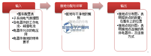
1. Single-wire system and negative ground There are two important concepts in the whole vehicle ground system: single-wire system and negative ground. Single-wire system refers to the fact that only one wire is used to connect the power supply to the electrical equipment in the automotive electronic system, while the metal body such as the automobile body, chassis, and engine is used as another common wire. Because the single-wire system saves wires, the circuit is simplified and clear, the installation and maintenance are convenient, and the electrical components do not need to be insulated from the car body, the single-wire system is generally used in modern automobile electrical systems. When the automobile electrical system adopts a single-wire system, one electrode of the battery is connected to the car body, commonly known as "grounding". If the negative electrode of the battery is connected to the car body, it is called negative electrode ground, otherwise it is called positive electrode ground. According to national standards, domestic automobile electrical systems all use negative ground. 2. Classification and introduction of grounding points 1) Zero potential on the negative pile head of power grounding battery. 2) The whole vehicle is grounded. The body sheet metal, chassis or engine parts, etc. that are conductive to each other on the whole vehicle. 3) The power signal grounds the power feeder of various electrical components on the whole vehicle. According to the magnitude/waveform of the current in the loop, it can be classified as "dirty ground" or "clean ground". Clean ground: Ground with a peak current of less than 1 A, such as sensor signal feedback or control signals between different components (e.g. network communication). Dirty ground: Pulse width modulated loads with peak current greater than 1 A and switching loads greater than 1 A, such as motor class and switching class loads. 4) RF ground is often used as ground to control RF interference. This kind of ground is generally installed directly on the body sheet metal through assembly, and cannot be used as a bypass for any ground current. 5) Antenna grounding, such as radio antenna grounding. 3. Ground distribution design process 4. Ground distribution Consider the vehicle installation position of electrical components, and combine the load type of electrical components and the specific ground category to design the ground distribution of each electrical component. 4.1 General Principle 1) Lay the railway nearby. Shorten the length of the ground loop as much as possible, and reduce the voltage drop, cost and quality of the loop. 2) Reduce unnecessary mutual interference between subsystems as much as possible. 4.2 Principle of interference Ideally, each electrical component needs to be grounded separately nearby. However, this will cause too much grounding of the whole vehicle, greatly increase the complexity of assembly, and increase the quality and cost of the whole vehicle. Therefore, this method is not the best choice. When setting the ground, it is necessary to consider sharing and merging the ground. Fig. 2 is a ground merging interference diagram when only part 1 is working, I1 = U/(L1+R1); When only part 2 is working, I2 = U/(L1+L2+R2); When both parts are working, I1+I2 = U/(L1+R1) + U/(L1+L2+R2). At this time, if I2 is significantly greater than I1, the potential difference between part 1 and ground will increase greatly, which will affect its normal operation. R1-the resistance of part 1, L1-the resistance of the wire from the riveting point to the ground point, R2-the resistance of part 2, L2-the resistance of the wire from part 2 to the riveting point. Figure 2 Ground combined interference diagram The usual design specifications will prohibit dirty ground and clean ground from being riveted together. If the difference between the high and low ground currents exceeds 1/5, the two ground circuits cannot be riveted together. However, please note that this is only a fairly conservative design specification. If these two circuits are thoroughly analyzed, they can be riveted together. From the above analysis, it can be known that in order to minimize the interference caused by riveting, the value of L1 should be reduced as much as possible, that is, the resistance between the riveting point and the ground should be reduced. Therefore, the riveting point should be as close as possible to the ground plate, and the wire diameter of this section should be increased if necessary. 4.3 Connection modes of several grounding circuits 4.3. 1 Combination of grounding by riveting points (Figure 3) Figure 3 Combination of grounding modes by riveting points The first way of riveting between clean grounding circuits is allowed, and the second way of riveting between dirty grounding circuits needs to be analyzed according to the method in 4.2. If it passes, it is completely acceptable. For the third way of riveting dirty grounding and clean grounding circuits, it is usually not allowed, unless it is approved by experts. 4.3. 2 Adopt the joint grounding combination form of grounding pieces (Figure 4) Figure 4 The first way is to clean the grounding terminal overlap between grounding circuits by combining grounding pieces; The overlap of ground terminals between the second kind of dirty ground circuits is also completely acceptable; For the third type of overlap between dirty ground and clean ground terminals, it is usually acceptable, but it needs to be reviewed and approved by relevant professionals. 4.3. 3 The form of crimping the ground terminal together at the ground end (Figure 5) The first way is to clean the parallel connection of the circuits between the ground circuits; It is also completely acceptable to connect the circuits in parallel between the second dirty ground circuits; It is usually acceptable to connect the third type of dirty ground and clean ground circuit in parallel, but it needs to be reviewed and approved by relevant professionals. 5. Requirements for grounding points 1) The location of the grounding points should be convenient for installation and maintenance, and the overlap surface should meet the torque requirements. 2) Each ground point should not be connected to more than 2 lugs. 3) Grounding points should not be arranged in strong splash areas and water accumulation areas. 4) Grounding points are not allowed to be arranged on metal parts connected by bolts, such as doors. When the instrument panel skeleton is provided with a ground point, it is only allowed if it is welded to the vehicle body. 5) For places where the body sheet metal thickness is less than 3mm, it is recommended to use a welding nut solution. For thick plates larger than 3mm, it is recommended to use self-tapping screws for ground installation. 6. General ground distribution principles 1) Engine ECU, ABS and other electrical components (such as audio, oil level sensor, etc.) that have a great impact on the performance and safety of the whole vehicle and are easily interfered by other electrical equipment must be grounded separately. 2) For the airbag system, the grounding point should not only be set alone, but also a composite grounding point should be used. The purpose is that when one of the grounding points fails, the system can be grounded through another grounding point to ensure the safe work of the system. 3) In order to avoid interfering with other systems, radio frequency signals need to be grounded separately. 4) The grounding of the weak signal sensor should be independent, and the grounding point should be close to the sensor to ensure the true transmission of the signal. 5) Other electrical components can be combined with each other to share the ground point according to the specific layout. The principle is to ground the ground nearby to avoid unnecessary voltage drop caused by too long ground wire. 6) Battery negative wire, engine ground wire, etc. have a large cross-sectional area, so the length and direction of the wire must be controlled to reduce voltage drop; In order to increase safety, the engine and car body are generally connected to the negative electrode of the battery separately. 7) It is necessary to distinguish electronic ground from power ground, and separate analog signal ground from digital signal ground to avoid mutual interference between signals.
---------------------------------------------------------------------------------------------------------------------------------------------------------------------------------------------------------------------------------------------------------------------------------------------------------- If you have related [connector wiring harness and cable products] purchasing/purchasing needs or want to purchase/understand which connector wiring harness and cable product solutions we can provide, please contact our business staff below; If you have related [Connector Wiring Harness Cable Products] sales/resources and promotion needs, please click "→ Business Cooperation ←" to negotiate with a dedicated person!
“Without the consent or authorization of this site, no one shall reproduce, reprint, distribute, cite, change, broadcast or publish the content in whole or in part in any form, nor shall there be any other violation of the copyright of this site.