Categorization:Product Information
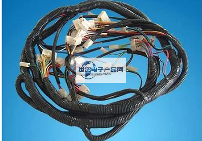
The after-sales market often reports unstable electrical functions or failures caused by poor contact of some wiring harness connectors. There are many reasons for this kind of problems, such as connector deformation, excessive fitting clearance of connector, unreliable fixation of connector, incorrect installation position, foreign matter in terminal contact position, damage during assembly process, too small plugging and pulling force, etc. Three aspects of terminal deformation, connector structure and selection, process design and control are analyzed and discussed.
-------------------------------------------------------------------------------------------------
1. Terminal deformation problem 1. The deformation of the elastic structure of the female terminal leads to the virtual connection with the male terminal, as shown in Figure 1. 2. Impurities enter the contact position of the male and female terminals, which affects the conduction performance of the terminals. 3. The problem of male terminal deformation (forward and backward, left and right skew) is shown in Figure 2. Figure 1 Example of female terminal deformation Figure 2 Example of male terminal deformation Male terminal deformation (forward and backward, left and right skew) generally causes the following problems: 1. The terminal bends or breaks when the sheath is butted; See Figure 32. The terminal enters other gaps, causing open circuit, short circuit or virtual connection. Fig. 3 Terminal bending caused by sheath butting. The deformation of the male terminal (forward tilt, backward tilt, left and right tilt) is generally caused by unreasonable manufacturing, packaging and assembly. But it also has a certain relationship with the structure and design selection of products. 2. In terms of product structure, the male terminal can be regarded as a cantilever beam structure in the sheath. The terminal skew is the deflection change of the cantilever beam in the stress direction. According to the calculation formula of deflection, deflection is directly proportional to the magnitude of the force and the size of the force point from the support point, and inversely proportional to the cross-sectional area and elastic modulus (affected by the material). It can be analyzed that the terminal selection will affect the terminal deformation in the following aspects. 1. The width and thickness of the terminal are small. Generally, small terminals, especially 1.0 and 0.64 type terminals of 1.5 and below, the thickness of the pin-shaped part of the terminal is generally only 0.6 mm, so the smaller the width of the terminal, the lower the bending strength of the terminal, and the easier it is to cause bending. 2. Terminal material Soft terminal materials are generally copper, brass, phosphor bronze, alloy copper, steel, etc. Copper has the smallest hardness, and the material directly affects the elastic modulus. Therefore, the softer the terminal, the worse its ability to resist deformation, and the easier it is to cause bending. 3. Long terminal size. The longer the terminal size, the longer the force arm. When the top of the terminal is stressed, the greater the deformation of the top. Countermeasures: 1. Try to choose terminals with larger width, but it is not conducive to the requirements of miniaturization and lightweight; Consider widening the terminal root or adding stiffener structure. Fig. 4 Terminal root structure 2. Choose phosphor bronze or alloy terminals with harder materials, but the conductivity of such terminals is slightly worse; Generally, folded pin terminals are replaced with integral pin terminals. Figure 5 Integrated pin-shaped terminal Figure 5 Physical parameters of each copper material 3. When the contact area is reasonable, try to choose a short terminal, or increase the structure to shorten the stress dimension, such as adding an anti-bending structure at the top of the terminal. Figure 6 Sheath with terminal anti-bending structure 3. Matching between terminal and sheath In terms of matching male and female end sheaths, the smaller the terminal width, the higher the verticality requirement of the terminal. Therefore, the smaller the terminal, the higher the stability requirement in the sheath after implantation. The influence of terminal skew on the matching between terminal and sheath: 1. Poor matching between terminal and sheath. The amount of shaking of terminal in sheath is large, regardless of the horizontal or vertical direction. If it exceeds the hole boundary of the female end, it will It is easy to cause the terminal to be bent during docking. 2. The lateral force of the terminal generally appears on the terminal at the edge of the sheath. Since the wire harness is bundled at the tail of the sheath in a triangular or side outlet type, the lateral tension of the terminals on both sides is relatively large. If the matching between the sheath and the terminal is poor, the terminals in these parts will deviate from the female end docking hole. 3. The number of holes in the sheath is large, and the insertion force is large. The more holes in the sheath, the greater the insertion force between the male and female ends. At the same time, due to the large volume of the sheath, it is easy to cause non-vertical docking during operation, and the male terminal is blocked by the female end. When the sheath is docked, the needle will be retracted or squeezed and deformed. Countermeasures: 1. Male and female end sheath manufacturers are consistent with terminal manufacturers, and mixing is prohibited. 2. Choose a connector with a secondary locking structure to reduce the amount of terminal shaking. 3. It is preferable to have strong guiding and error-proof structures, especially the female end hole should have a butt-joint guiding structure (such as a funnel-shaped inclined surface). At the same time, the top end of the male terminal is designed to be a needle tip shape. Fig. 7 Guide structure of terminal socket 4. Appropriately relax the bare wire allowance at the tail of the sheath to reduce the stress on the wires on both sides. Pay special attention to the side outlet sheath, and the distal wire should have a certain curvature. Fig. 8 It is recommended to choose a porous sheath for the bare wire allowance at the tail of the sheath. Try to choose a sheath with a power-assisted structure. This kind of sheath has a slow docking speed and uniform terminal stress. Generally, the power-assisted structure can only be used after the male and female ends are installed vertically. Figure 9 Tie rod sheath IV. Front and rear engineering process design. Front engineering process 1. The design of terminal crimping parameters is unreasonable, and the terminal head is tilted forward and backward. Such problems are easy to find, and the probability of occurrence is small. Some terminal drawings will also give reasonable height and width value selection requirements. Fig. 10 Poor terminal crimping 2. Unreasonable selection of terminal insulation crimping shape. Unreasonable setting of height and width value of terminal insulation part and unreasonable design of crimping shape will cause a large amount of shaking of terminal in the sheath, which will lead to the terminal easily deviating from the butt hole position when the sheath is butted. Fig. 11 Post-engineering process of terminal insulation crimping shape example 1. The forward insertion rate of male terminals is low, the operation rhythm on the assembly line is short, and 100% vertical insertion cannot be guaranteed. A large number of male terminals are inserted into the assembly line, which can easily cause the terminals to be inserted crooked, especially the male terminals with small width and thickness are more likely to be inserted. 2. The wiring sequence design causes the male terminal to wait for operation. The wiring sequence design is unreasonable. The uninserted male terminal is routed first, and then the sheath is arranged for the terminal to be inserted, which can easily cause the terminal to be extruded and deformed on the fixture. Countermeasures: 1. Reasonably design the crimping parameters and design the necessary inspection tools to prevent the terminals from leaning back and forth. 2. Reasonably design the crimping shape of the terminal insulation parts to reduce the moving space of the terminals in the sheath. 3. Improve the forward insertion rate of male terminals, and try to make male terminals work on the sub-assembly platform to ensure vertical insertion. At the same time, it can reduce the extrusion deformation caused by bundling and transporting of terminals from sub-assembly to final assembly. 4. Adjust the wiring sequence. If the forward insertion rate of male terminals cannot be 100% guaranteed, especially for terminals with smaller terminal thickness and width, wire the sheath end of male terminals first. Such male terminals of the later cloth are immediately inserted into the sheath. 5. Manufacturing process All aspects of the manufacturing process may cause terminal deformation, especially the crimping, implanting and handling processes. The main reason why the crimping station easily causes terminal skew is that the control and protection of the crimping process are not in place. Countermeasures: It is necessary to add a protective cup to the crimped finished product. In addition, it is necessary to pay attention to the problem of the terminal tilting back and forth during the terminal crimping process. Use professional inspection tools designed and manufactured for the male terminals that are prone to tilting back and forth, and carry out the random inspection control of the first, middle and final products crimping forward and backward, so as to filter out 99% of hidden dangers from the beginning. During the handling process of sub-packaging and sub-packaging stations, attention should be paid to the process protection of terminals to prevent them from being squeezed. Problems that are easy to occur in the sub-packaging process: 1. Terminal hook deformation during the sub-packaging process; 2. The planting operation is not standard, and non-vertical insertion leads to deformation. Countermeasures: The sub-assembly station should pay attention to the standardization of operations, give priority to inserting the male terminal side, ensure vertical insertion, and pay attention to the terminal status after implantation. In addition, the design and rational use of interpolation tooling will reduce the occurrence of defective rate. Final assembly Final assembly is greatly affected by the operation sequence, which is generally the terminal skew problem caused by the post-insertion operation of male terminals. 1. The wiring sequence is unreasonable, and the male terminal is hung on the board first, and it is squeezed and deformed when it is snapped into the fixture; 2. The male terminal is located in an area with dense wires and is easily touched or pulled and deformed by other wires or plug-ins when wiring. 3. The planting operation is not standard, and non-vertical insertion leads to deformation. Countermeasures: Resolutely abide by the process design sequence, reduce the planting operation of male terminals in final assembly, pay attention to the standardization of vertical planting operation, and conduct self-inspection of the status of terminals after planting. Electrical inspection The electrical inspection platform is not equipped with vertical inspection or the detection tolerance of the vertical inspection module is too large. Some electrical detection modules can only detect the skew in the vertical direction, but the skew in the horizontal direction cannot be detected. Countermeasures: Reasonably select and design the vertical detection module of the electric inspection platform, and try to reduce the size of the detection position. After the electrical examination is completed, the auxiliary correction fixture can be used for correction. 6. In terms of packaging and OEM final assembly, the male connector with more packaging holes and larger sizes is easily embedded in the cavity by other small parts, causing the terminal to be extruded and deformed. Countermeasures: Try to protect the larger male connector independently, add a protective cover or wrap it in a bag. The unreasonable assembly design structure of wire harness leads to blind insertion and non-vertical butt-joining of male and female ends, which easily leads to extrusion deformation of terminals. Countermeasures: For connectors with more holes and smaller male terminals, priority should be given to designing more assembly space. Before assembly, check whether the male terminals are non-parallel, standardize the assembly operation, and butt them vertically. Use uniform force during operation, and assemble without violent assembly.
---------------------------------------------------------------------------------------------------------------------------------------------------------------------------------------------------------------------------------------------------------------------------------------------------------- If you have related [connector wiring harness and cable products] purchasing/purchasing needs or want to purchase/understand which connector wiring harness and cable product solutions we can provide, please contact our business staff below; If you have related [Connector Wiring Harness Cable Products] sales/resources and promotion needs, please click "→ Business Cooperation ←" to negotiate with a dedicated person!
“Without the consent or authorization of this site, no one shall reproduce, reprint, distribute, cite, change, broadcast or publish the content in whole or in part in any form, nor shall there be any other violation of the copyright of this site.